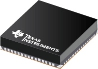
Datasheet Texas Instruments LMZ31530 — Datenblatt
| Hersteller | Texas Instruments |
| Serie | LMZ31530 |

SIMPLE SWITCHER® 3V bis 14,5V, 30A Leistungsmodul in kleinem QFN-Paket
Datenblätter
LMZ31530 30-A SIMPLE SWITCHERВ® Pwr Module w/ 3-V to 14.5-V Input datasheet
PDF, 825 Kb, Revision: C, Datei veröffentlicht: Jun 6, 2017
Auszug aus dem Dokument
Preise
Status
| LMZ31530RLGT | |
|---|---|
| Lifecycle Status | Active (Recommended for new designs) |
| Manufacture's Sample Availability | Yes |
Verpackung
| LMZ31530RLGT | |
|---|---|
| N | 1 |
| Pin | 72 |
| Package Type | RLG |
| Industry STD Term | B4QFN |
| JEDEC Code | R-PQFP-N |
| Package QTY | 250 |
| Carrier | SMALL T&R |
| Device Marking | LMZ31530 |
| Width (mm) | 15 |
| Length (mm) | 16 |
| Thickness (mm) | 5.8 |
| Pitch (mm) | .8 |
| Max Height (mm) | 5.9 |
| Mechanical Data | Herunterladen |
Parameter
| Parameters / Models | LMZ31530RLGT |
|---|---|
| Iout(Max), A | 30 |
| Operating Temperature Range, C | -40 to 85 |
| Package Size: mm2:W x L, PKG | 72BQFN: 240 mm2: 15 x 16(BQFN) |
| Package Type | QFN |
| Regulated Outputs | 1 |
| Soft Start | Adjustable |
| Special Features | EMI Tested,Enable,Light Load Efficiency,Power Good,Remote Sense |
| Switching Frequency(Max), kHz | 850 |
| Switching Frequency(Min), kHz | 300 |
| Switching Frequency(Typ), kHz | 500 |
| Vin(Max), V | 14.5 |
| Vin(Min), V | 3 |
| Vout(Max), V | 3.6 |
| Vout(Min), V | 0.6 |
Öko-Plan
| LMZ31530RLGT | |
|---|---|
| RoHS | Not Compliant |
Anwendungshinweise
- Working With QFN Power Modules (Rev. A)PDF, 1.7 Mb, Revision: A, Datei veröffentlicht: Jun 8, 2017
TexasInstrumentsQuadFlatpackNo-lead(QFN)powermodulesallowfor boardminiaturization,and holdseveraladvantagesoverotherpowermodulepackages.The QFNpackageshavehigherpowerdensity,asmallerroutingarea,improvedthermalperformance,and improvedelectricalparasitics.Additionally,theabsenceof externalleadseliminatesbent-leadconc - Soldering Requirements for BQFN Packages (Rev. B)PDF, 737 Kb, Revision: B, Datei veröffentlicht: Jun 8, 2017
This documentoutlinesthe solderingrequirementsfor the TPS84and LMZ3devicefamilies - Uninterruptible Synchronization Clock CircuitPDF, 74 Kb, Datei veröffentlicht: Nov 22, 2013
- AN-2155 Layout Tips for EMI Reduction in DC/ DC Converters (Rev. A)PDF, 3.6 Mb, Revision: A, Datei veröffentlicht: Apr 23, 2013
This application note will explore how the layout of your DC/DC power supply can significantly affect theamount of EMI that it produces. It will discuss several variations of a layout analyze the results andprovide answers to some common EMI questions such whether or not to use a shielded inductor. - AN-1520 A Guide to Board Layout for Best Thermal Resistance for Exposed Packages (Rev. B)PDF, 9.2 Mb, Revision: B, Datei veröffentlicht: Apr 23, 2013
This thermal application report provides guidelines for the optimal board layout to achieve the best thermalresistance for exposed packages. The thermal resistance between junction-to-ambient (ОёJA) is highlydependent on the PCB (Printed Circuit Board) design factors. This becomes more critical for packageshaving very low thermal resistance between junction-to-case such as exposed pad TSSOP - AN-2162 Simple Success With Conducted EMI From DC-DC Converters (Rev. C)PDF, 2.5 Mb, Revision: C, Datei veröffentlicht: Apr 24, 2013
Electromagnetic Interference (EMI) is an unwanted effect between two electrical systems as a result ofeither electromagnetic radiation or electromagnetic conduction. EMI is the major adverse effect caused bythe application of switch-mode power supplies (SMPS). In switching power supplies EMI noise isunavoidable due to the switching actions of the semiconductor devices and resulting disconti - Semiconductor and IC Package Thermal Metrics (Rev. C)PDF, 201 Kb, Revision: C, Datei veröffentlicht: Apr 19, 2016
- QFN and SON PCB Attachment (Rev. B)PDF, 821 Kb, Revision: B, Datei veröffentlicht: Aug 24, 2018
- Input and Output Capacitor SelectionPDF, 219 Kb, Datei veröffentlicht: Sep 19, 2005
Modellreihe
Serie: LMZ31530 (1)
Herstellerklassifikation
- Semiconductors> Power Management> Power Modules> Non-Isolated Module> Step-Down (Buck) Module