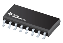
Datasheet Texas Instruments TL494IDRG4 — Datenblatt
| Hersteller | Texas Instruments |
| Serie | TL494 |
| Artikelnummer | TL494IDRG4 |

PWM-Steuerkreis 16-SOIC -40 bis 85
Datenblätter
TL494 Pulse-Width-Modulation Control Circuits datasheet
PDF, 1.3 Mb, Revision: H, Datei veröffentlicht: Feb 27, 2017
Auszug aus dem Dokument
Preise
Status
| Lifecycle Status | Active (Recommended for new designs) |
| Manufacture's Sample Availability | No |
Verpackung
| Pin | 16 |
| Package Type | D |
| Industry STD Term | SOIC |
| JEDEC Code | R-PDSO-G |
| Package QTY | 2500 |
| Carrier | LARGE T&R |
| Device Marking | TL494I |
| Width (mm) | 3.91 |
| Length (mm) | 9.9 |
| Thickness (mm) | 1.58 |
| Pitch (mm) | 1.27 |
| Max Height (mm) | 1.75 |
| Mechanical Data | Herunterladen |
Parameter
| Control Method | Voltage |
| Duty Cycle(Max) | 45 % |
| Frequency(Max) | 300 kHz |
| Frequency(Min) | 1 kHz |
| Gate Drive(Typ) | 0.2 A |
| Operating Temperature Range | -40 to 85,0 to 70 C |
| Package Group | SOIC |
| Rating | Catalog |
| Special Features | Adjustable Switching Frequency,Error Amplifier,Multi-topology |
| Topology | Boost,Buck,Flyback,Forward,Full-Bridge,Half-Bridge,Push-Pull |
| UVLO Thresholds On/Off | N/A V |
| Vin(Max) | 38 V |
| Vin(Min) | -0.3 V |
Öko-Plan
| RoHS | Compliant |
Anwendungshinweise
- Isolated Multiple Output Flyback Converter Design Using TL494PDF, 741 Kb, Datei veröffentlicht: Jun 18, 2014
- Off-Line SMPS Failure Modes PWM Switchers and DC-DC ConvertersPDF, 71 Kb, Datei veröffentlicht: Mar 22, 2000
Today's voltage regulator modules (VRMs) employ off-line SMPS techniques. Traditionally, they are usually discarded when they fail because they are so challenging to debug and so inexpensive to replace. Investigation of these failed modules reveals some common failure modes. Some failures are caused by other systems' passive components that fail after repeated electrical stress. Recognizing these - Designing Switching Voltage Regulators With the TL494 (Rev. E)PDF, 329 Kb, Revision: E, Datei veröffentlicht: Jul 26, 2005
Designing Switching Voltage Regulators With the TL494 - Understanding Buck Power Stages In Switchmode Power SuppliesPDF, 173 Kb, Datei veröffentlicht: Mar 4, 1999
A switching power supply consists of the power stage and the control circuit. The power stage performs the basic power conversion from the input voltage to the output voltage and includes switches and the output filter. This report addresses the buck power stage only and does not cover control circuits. Detailed steady-state and small-signal analysis of the buck power stage operating in continuous - Understanding Boost Power Stages In Switchmode Power SuppliesPDF, 149 Kb, Datei veröffentlicht: Mar 4, 1999
A switching power supply consists of the power stage and the control circuit. The power stage performs the basic power conversion from the input voltage to the output voltage and includes switches and the output filter. This report addresses the boost power stage only and does not cover control circuits. The report includes detailed steady-stage and small-signal analysis of the boost power stage o - Understanding Buck-Boost Power Stages in Switchmode Power Supplies (Rev. A)PDF, 363 Kb, Revision: A, Datei veröffentlicht: May 28, 2002
Modellreihe
Serie: TL494 (25)
Herstellerklassifikation
- Semiconductors > Power Management > Offline and Isolated DC/DC Controllers and Converters > PWM and Resonant Controller